![]()
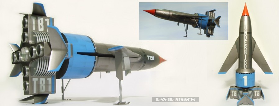
Scratchbuilding Thunderbird 1 from Gerry Anderson's classic 60s TV show
 |
One of the most successful elements to the 'Thunderbirds' television series was the fact that each of the Tracy brothers had their own distinctive vehicle to pilot, and that each one of these craft just had to become some child's favourite toy - even Thunderbird 5! However the constant 5-4-3-2-1 countdown every week also tended to sell the craft as a set, so it was never good enough to just have one or two of them. Although my parents bought me a number of these toys I never did manage to get them all, which might account for the fact that over the last 30 years I've had this constant urge to build the Thunderbird models - even though its far from being my favourite Gerry Anderson series. |
 |
 |
The number one problem with scratchbuilding models is acquiring information, photographs and blueprints. However due to Thunderbird 1's simple shape you can just about construct an accurate replica from one good profile shot. Luckily Thunderbird 1's main publicity photograph consists of it hanging in mid-air in almost perfect profile - so it's not too difficult to get hold of such a thing. The blueprint is the most important stage of the whole process and I often spend many hours drawing and redrawing my plans until I am satisfied with them. Not that they have to be that detailed, usually all you need is a couple of outline drawings and not always complete ones at that. My mistake when I first started to scratch-build models was to draw complete plans, from all angles, that included every detail - by the time I had finished I had lost interest in building the darn thing! Size is the next problem, there's nothing worse than spending months or years building an extra special piece of model making excellence only to realise you wanted it twice the size or that its too big to handle! Although I wasn't building my set of Thunderbird models to the same scale I did want them to look right when displayed next to each other - I didn't want a situation where they are the same size or TB1 is bigger than Thunderbird 2, which would just look odd. As my TB2 and TB3 were in the 30-40 inch range I finally settled on a length of 27 inch's. The next question was which version of Thunderbird 1 was I going to make? Generally speaking I tend to consider the original set of studio models to be the definitive versions, as the many duplicates built during the course of the series often had a different shape, markings and surface detailing. So my model would be a copy of that 16" model that you see taking off each week - except for the removable section on the main hull which I hate, as it results in a very obvious join line which I think ruins the design. This would make my model look more like the largest studio miniature that the film makers used for the close-up landing shots and as I was going through my photo collection, I realised that I liked the model with its landing gear down so I changed my plans and built that version instead. The Build .by David Sisson .....Also see FAB Magazine issue 41 |
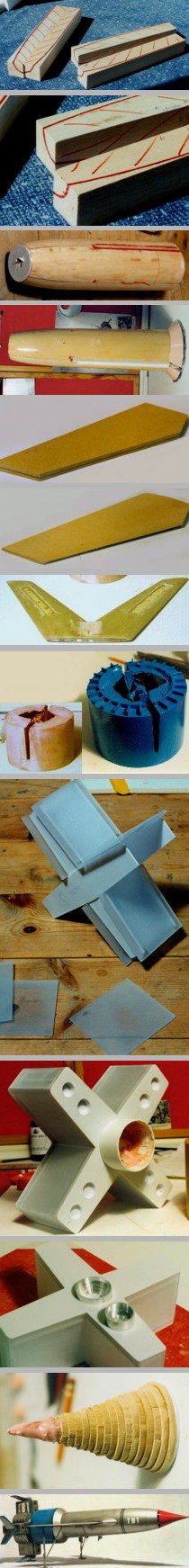
I began construction by making the main fuselage out of balsa wood. Making the tapering shape out of a block of balsa would have been difficult so I used four 2" square lengths. The outline of the hull could be drawn onto the inner sides and the excess wood trimmed away before gluing them together. This gave me the basic shape of the hull and saved a lot of time. Plastic discs were glued to each end to indicate the diameters required and then I had to spend several days sanding it down to the required shape. My original plan was to make plaster moulds and produce the final model in fibreglass but I wanted to save weight and as I only intended this to be a one-off decided to use the wooden master as the final model. To do this I needed to
give the soft wood a tough outer skin. Firstly the
plastic discs were removed and the slot for the wings was
sawn out. Then a large Perspex disc was glued to the back
end to form the wide part of the fairing - which itself
would be formed in P38 car filler. The wings themselves
were going to be made from Perspex but I decided to use
MDF instead, as it is a lot easier to shape. Also I
needed to channel out a slot in the wings to accept the
undercarriage and that would have been hard work with
Perspex. In the photo a centre line has been drawn around
the wings to act as a guide whilst sanding - only a few
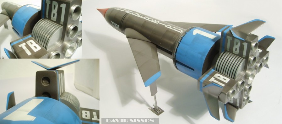
minutes work on a belt sander. As the wings were going to support the model any idea of making them able to retract was abandoned - luckily I have a second model that can be displayed in the take-off and flight mode. Some of the studio models had lines on the wings, panel lines and the outlines of the ailerons, but I didn't want to etch these in or draw them on in biro. So instead I made them in the painting stage by applying thin tapes to the wings after the first coat of silver, then after spraying on two more coats the tapes were removed to leave nice neat lines in the surface. The blue drum-shaped centre section was the next piece to be made. My first thought was to use a short length of EMA plastic pipe but I was worried about paint chipping off while I handled it in the future. As this is usually the area to hold the model I wanted it to be strong, so the idea of making it in fibreglass seemed best. As it happened I had some plastic pipe that's inside diameter was the right dimension, so I waxed the interior and used it as a mould to make the part. After it had set the plastic tube was split and the part removed, cleaned up and any small holes filled with knifing putty and spray filler. The tail section was the easiest to build as it is all flat sides, that could just be made from sheet plastic. Construction began with the formation of an internal cross-shaped 2mm Plasticard frame with 12 Perspex pieces then glued around it. Thin Plasticard was then used to cover each end into which the intake and exhaust holes were carefully cut. The secret with holes is never to cut out the size you need but to start by making a smaller hole and then enlarging it, this allows for shape and positional alterations. My grand plan with this
model was to make all the exhaust tubes on my old lathe
but after spending several hours of effort all I had to
show for it was the one large central tube and a lot of
mangled bits of metal. So all the other tubes were made
from modified kit parts and Plasticard. The large cooling vanes proved to be a bit of a pain, I cut them from ten Plasticard discs and assembled them in position with more strips of plastic in between as spacers. Then realised that they looked slightly on the thin side, so I had to disassemble the areas and glue every part to a thin sheet of plastic to increase the thickness. Finally the small v-shaped fins were cut and sanded to shape out of MDF, again coated in resin for a smooth finish. Each pair of fins were glued together and blended into one piece with filler. Then they were painted and glued to the finished model - then carefully broken off and reattached with a dab of superglue. It sounds a bit strange but experience tells me that certain parts of models usually break off and so its better to pre-break them so that when the model receives a knock the parts fall harmlessly off without sustaining any real impact damage. One part of the model
that I had not been looking forward to making was the
nosecone, which I had planned to do on my lathe, but as
that wasn't working another plan was needed. A fellow
modeller suggested using a series of discs glued on top
of each other to form the basic shape. While this sounded
as if it might work I was worried that there wouldn't be
enough strength in the part and that the tip would break
off. So I ended up drilling holes in the centre of all my
discs and assembling them on a brass rod that ran up the
centre and formed the tip itself. The final part to be made was the undercarriage which was assembled from a collection of brass strips, rods and tubes. Although I had a couple of pictures of these parts I wasn't entirely sure of what I was seeing due to the thin bent angular nature of the design. So this turned into one of those 'lets fast-forward through my video collection' sagas in the hope of seeing some more detail. The smaller studio model had a very simple undetailed undercarriage that was often put on back to front, while the big models seemed to change from episode to episode as bits fell off! I did finally manage to figure out the design and after three adjustments got the model to sit straight. However the design means that the main legs are set quite a way back down the model very close to the centre of gravity, and the thin wings tend to want to bend under the strain - so while the whole thing looks nice it's not really a very good design! |
|
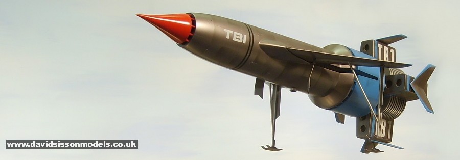
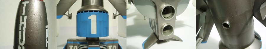
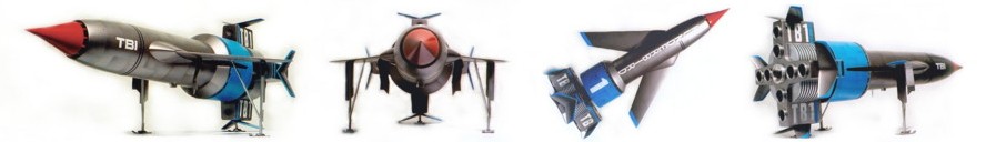
The model was painted with cellulose motorcar spray paints and weathered with enamel paints applied with an airbrush. The white lettering was either painted on or cut from white self-adhesive paper sheets. Black lines were Letraset flexline tapes. And finished - but unfortunately it just didn't look right. (picture right) When I make models I am always trying to correct any mistakes that I happen to make or throw parts away and start again if they don't turn out as expected - However its often only after the model is completely finished that you can really tell how good it is, and if it looks right compared to photographs of the originals. Sometimes you just fail! This model just looked wrong so it was a case of making a list of the faults and breaking it up and redoing it. One problem was the silver paint that should have been a darker aluminium colour. After all my efforts the nosecone turned out to be slightly too wide and merged with the shape of the hull - it should be thinner resulting in a noticeable lip. The white paper lettering that had worked so well on other models looked poor and so every letter needed to masked and spray-painted on. The blue drum section, while good, was too heavy and needed to be replaced with a plastic one after all. And finally the weathering was poor and so it was redone using graphite pencil and also cutting the panel lines into the paint surface with a knife to highlight them more. So just a strip down and rebuild and then finally finished. |
 |
 |