![]()
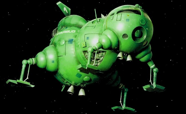
Scratchbuilding Starbug from Red Dwarf
|
|||
| (*Note photos are from two different builds) | |||
 |
|||
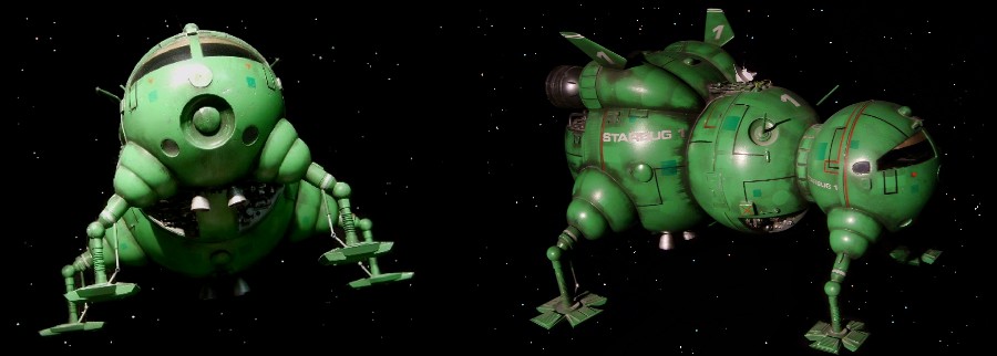 |
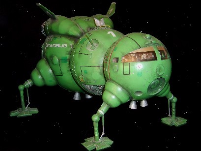
I had been collecting photographs of the original models for a while with the intention of building a replica Starbug but could never actually start the project because of the lack of a decent profile picture - or for that matter a usable blueprint. Then just before the Red Dwarf magazine folded it published an interview with the builder of the original model, Alan 'Rocky' Marshall. He stated that the models hull was mostly made from EMA Hemispheres supported on a steel structure. The three domes forming the main hull of the 1/25 scale model had diameters of 8", 10 " and then a special custom made 14" dome for the rear engine section - because that size could not be bought off the shelf. With this information I could start building. As usual the first question to answer is what size to build it? Normally I like to build to studio scale but I didn't like the choice of sizes, 30 inches was too big (as the rear legs are very widely spaced) and 15" was too small so I decided to pick my own size of around 22" in length.
The Build David
Sisson |
|
Unlike models that
require many hours of sculpting and shaping, Starbug is
simply a collection of hemispheres so all I had to do was
get out my EMA Catalogue and order the parts - or maybe
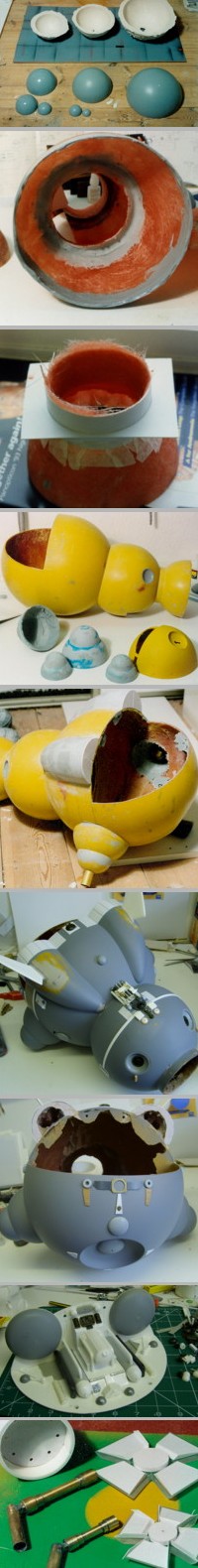
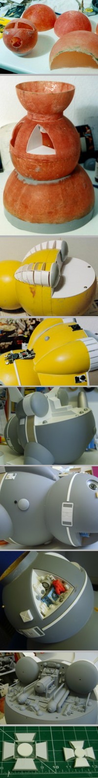
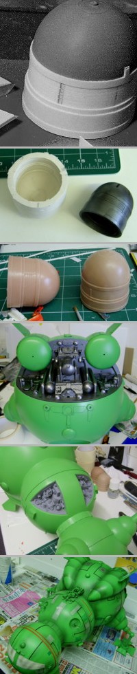
not. The surface of the dry plaster then needed to be sealed, or the resin binds to it, and to do this I just sprayed them with several coats of gloss car paint - I use my collection of almost empty spray cans. I then apply some wax to the painted surface and can begin putting the resin and glassfibre in, or in the case of the four leg supports just P38 car filler. I began assembling the model by supergluing two hemispheres together to form the midsection of the craft. Next the back half of the pilots cabin was attached by a short connecting piece. This was formed by making the circular shape in plastic sheeting and fixing it into position, then more fibreglass was added to the inside and when it had set the plastic was cut away. As each section was attached the connecting area inside was cut away to make the model hollow and P38 filler smeared along the inner edges to strengthen the joins and cover any sharp bits. As I wanted to install a detailed cockpit the front piece was left off till much later, so I now attempted to attach the rear engine sphere and ran into a small problem. The engine and central spheres merge together in an off-centre position that would need to be calculated carefully. I had actually started the project without a blueprint because I thought it was unnecessary. Lets face it the craft is just a 'bunch of balls' and I prefered to work out the details on the actual model and not on paper. So at this point I had to draw up an outline plan before I could proceed. With the exact position plotted a large circular hole was cut out of the engine dome and the midsection glued into place, more filler sealed all the gaps. The engine sphere is actually elongated slightly with the addition of a spacer section between the hemispheres. I formed this in the same way as the neck piece, running a strip of Plasticard in a loop around the edge and applying P38. The next step was to create the two big engine fairings that sprout out of the top of the model. These end at EMA elliptical spheres that attach to the engine nozzles. To begin with I attached the EMA parts to give me the finishing points, then plotted the start points. Now all I had to do was create the general shape of the fairings in Plasticard and then cover it all over in filler. When this was all sanded down the thin edges of the plastic showed in the surface so they had to be cut out and then the areas filled in to get a perfect finish. The rear leg supports were now added. Brass tubes are built into these supports to provide strong attachment points for the legs. Again where the sections join the outer body the inside areas are cut away and more resin or filler is applied to make a stronger connection. The fibreglass shell received several coats of spray filler and was rubbed down with wet & dry paper to a smooth finish. Then surface detailing was applied using Plasticard and assorted kit parts. One part I didn't make was the thin piece of framework which on the original model looked like a kit part from the 'Space 1999' Hawk kit. As I could not make a good copy I decided to leave it off as I find that people (and myself) can spot a badly made part very quickly but usually not a missing part! Above right; in this picture the two inset sections have been drilled out of the midsection and are being blocked out in Plasticard, then detailed with kit-parts. The two fins are made from two layers of 2mm Plasticard, sanded to an aerofoil shape and fixed deep into the fairings. The shape of the ailerons were cut and filed into the surface. The rear detailed engine
area is blocked out in thick Plasticard secured to the
hull with four screws, this will allow future access to
the inside - something that I have come to realise is a
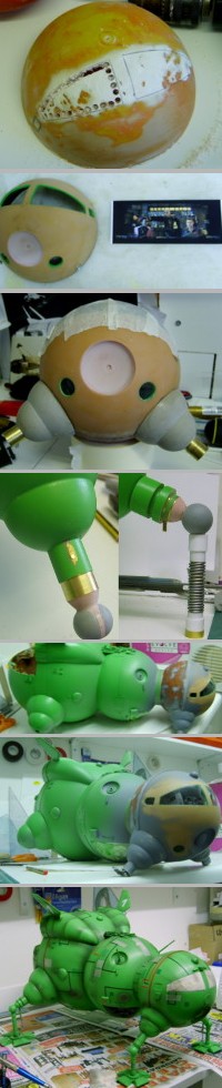
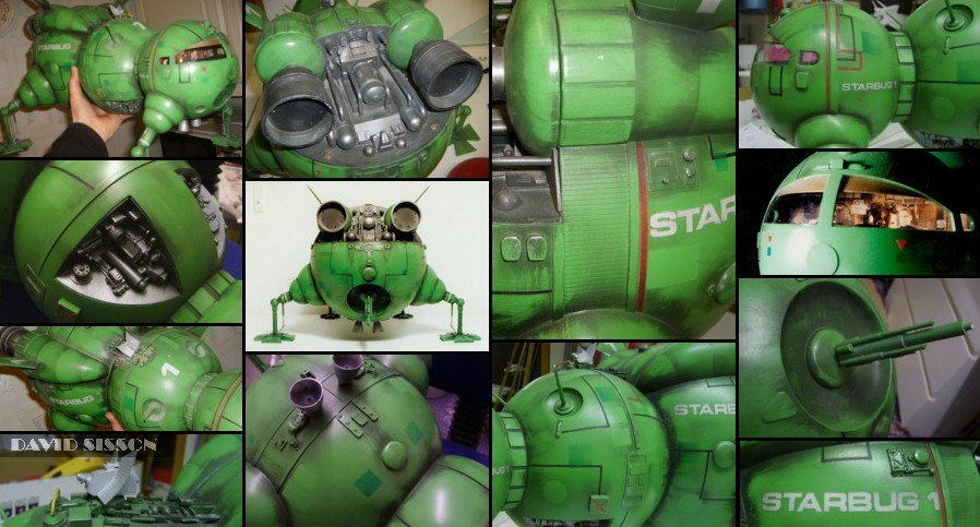
very handy thing to have with models. The four legs were now soldered together using Brass tubes and Carrs 188 solder paste from my local model shop. The feet were cut from 1/4" Perspex sheet, with the edges taken off using a belt sander, and then the top surfaces were detailed with Plasticard. The two engines were formed from EMA domes with short sections from a Space Shuttle external tank kit part, then detailed with strips of thin plastic. For the second model I took a rubber mould of one of these and then slush-moulded two resin copies. The windows, headlights and the 'mouth' area were now drilled out of the front hemisphere. The concave recess was made by holding a waxed EMA plastic dome in the hole while applying car filler from the inside - once this all set the EMA part was prised free. Most studio models either have no interior detail or just some crude figures installed. As the windows are quite big I needed to have something reasonable inside but the chances of me building decent figures of Rimmer, Lister, Cat and Kryten were rather slim. As it happened a front angled photograph of the live action set was published and I decided to copy it and fit it into position. As usual the set and model don't match and I had to use two pictures, cut up and spread apart to fill the area.This was then rephotographed cut out and fitted into position. The final effect is not what you would normally expect to see inside a model and works reasonably well. The leg tubes were glued into place and checked to make sure that they were perfectly vertical and not leaning at an angle. Then a small hole was drilled through them and a securing pin inserted to prevent the legs from rotating. To create the legs spring-suspension look I resorted to supergluing solder wire around the brass tubes - real wire wouldn't bend and hold the right shape. After the article on building my first Starbug model was published in Sci-Fi & Fantasy magazine I received an offer to visit the studio and look at the original models and noticed that I'd made a few mistakes. Overall shapewise the model was very good but there were a couple of detail errors. The two engine fairings don't actually feed into the midsection but round off just as they reach it - as these parts were just filler I could reshape them with ease. Details around the top radar section needed improving and corrugated Plasticard pieces had to be added to the tops of the feet. Also the general shape of the rear plastic engine unit was wrong and had to be stripped and redetailed. Overall the worst problem was the finish. I had painted the model using motor car spray paints - right colour but wrong semi-gloss finish as the original models had a very matt and battered finish. As a result the whole model was repainted and afterwards rubbed down with very fine wet & dry paper to get the dull look. The existing glossy coloured trimline tapes were replaced with matt Letraset Letraline ones. Finally the model was airbrushed with thinned down black enamel paint to mess it up,which was then partially wiped off with a tissue to create a streaked appearance. Finally some damage was inflicted to the model - little chips and scuff marks- and finally it began to really look like Starbug. |
|
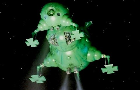
| The first models vertical jets were connected up to a series of tubes which allows me to pump airbrush propellant through them to simulate a rocket exhaust - unfortunately I've found that the gas doesn't really want to show up on still photographs unless its backlit. | 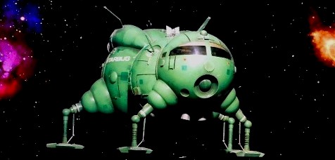 |
|