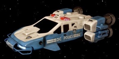
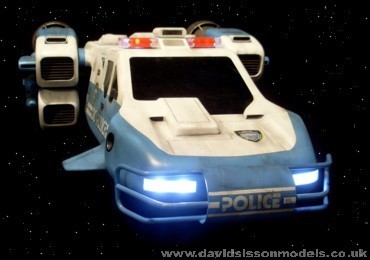
Chasing bad guys in the Precinct Cruiser from Gerry Anderson's Space Precinct

Back to INDEX

'Space Precinct', made back in the early 1990s, was Gerry Anderson's last major television series. It was spawned from an old Cop's-in-Space idea that he had come up with shortly after 'Terrahawks' had ended in the mid 1980s, which at the time had resulted from a failed pilot film called 'Space Police'.

That attempt also incorporated another of Gerry's old ideas of mixing his famous puppet work with live-action, which he had tried before with 'The Secret Service. However several years later he did manage to secure a deal on the basic space cops idea, a larger budget was acquired and so the puppets went out of the window as his live-action series, now renamed 'Space Precinct', began shooting.

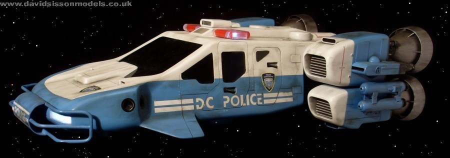
Like Gerry's past series each episode was to feature a wealth of special effects work achieved with good old-fashioned model work, and as the characters would need a fancy Sci-Fi vehicle to travel around in so the Precinct Cruiser was born. This craft was initially created by series Special Effects Director Steven Begg - see Space Precinct SFX interview - and was a streamlined combination of helicopter and Space Shuttle. However the Producers wanted something that looked more like a Police car - so a bonnet was stuck on the front!
The first model, built under the supervision of Modelshop Supervisor Bill Pearson, lost much of Steven's curvy design and became more angular in nature, possible to aid in construction and also more importantly saving future costs when a near full-size version would be constructed.
This initial 30" long prototype was actually used as a display model to sell the series at a trade show in the United States. Once funding had been secured this became the accepted design, although they were able to add significant modifications to give the rather basic vehicle a much more visually interesting and tougher overall appearance - especially with the addition of bull bars!

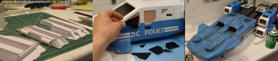
As usual I collected together a multitude of reference photographs to aid in my construction and managed to draw up a blueprint to a 
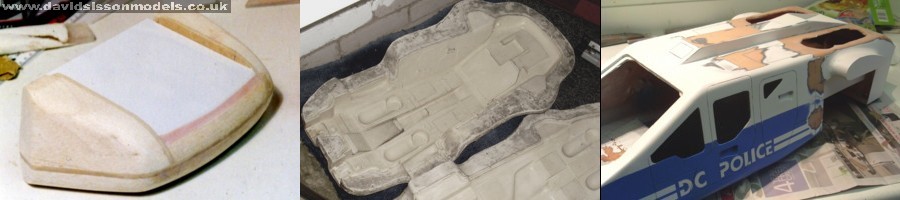
30" sized model. I began by blocking out the main hull in MDF sheeting; although the front bonnet area was done with MDF just forming the outline shapes and then adding Balsa wood sections to get the curvy edges. Things were going along reasonably well when a friend suddenly said 'Would you like to use the studio hull moulds?' Doh!
So my MDF build flew straight into the dustbin and all I had to do was casting up a copy .....easy .... or so I thought.
The original studio model had been a straight build in perspex, plastic sheeting, and car filler. This mould had been created from it to produce copies of in what I assume was a slush-moulding process, as there are two access holes in the rear. I decided to use my normal fibreglassing method which posed a small problem of actually how to do it in an enclosed mould. The obvious answer was to apply the fibreglass to each half separately, and after it had set clamp the two moulds together and pour resin in the end, then slosh it around the areas where the join is to bond the two halves together.
This sounded easy but there were a number of problems, with the main one being the mould holding the correct shape. The old rubber was quite thin and was supported by a fibreglass jacket. Whilst joined together they were fairly ridged by when split they both flexed, especially the top half. To fix this I used the boltholes to attached strips across the mould to brace the structure and ensure the castings had exactly the same width.
The other problem was the thin rubber lifting away from the jacket and distorting, so here I had to apply the fibreglass mixture one section at a time whilst applying gentle pressure to the rubber to get it to hold its true shape.

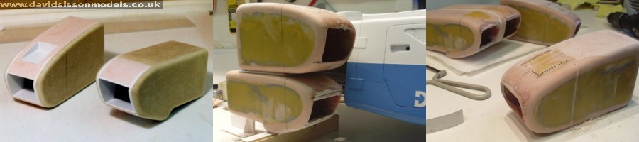
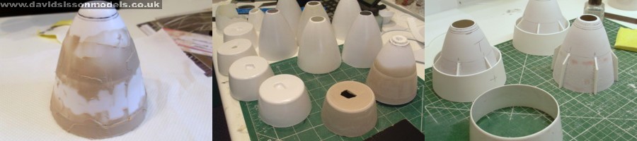
The resulting casting appeared to come out rather well, and filled with enthusiasm I quickly painted it in preparation for the next stage. However problems began to become evident with minor distortions in several areas, particularly under the nose and top rear section. Disillusioned by the project I put the casting on a shelf and forgot about it for six years!
After watching the series again I decided to have another go and reviewed the casting that I had. The distorted areas were cut away and levelled off, before reattaching modified pieces. As I dislike moulded on panels I sanded them all off the model and replaced them in plastic sheeting.
Picture above right: The detail under the rear is made by cutting up a 35mm film plastic slide holder, plus several EMA parts.

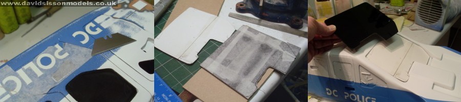
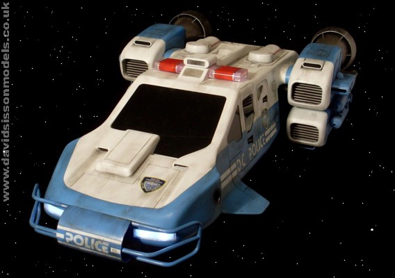
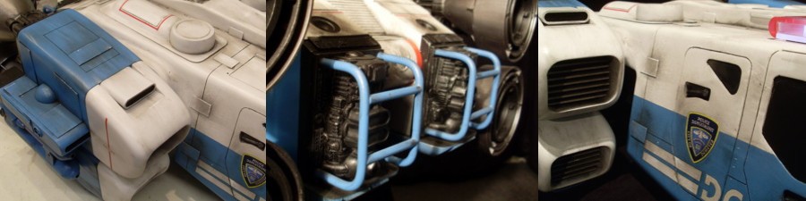
Above: the 'DC Police' lettering was simply done using the outlines in the surface casting. Masking tapes were applied to cover the white primer.
Like the original model the front windscreen area was removed from the casting and a Black perspex window dropped into position. Here I cut the shape from cardboard to create a template guide that I used to trim the perspex sheet. Masking tapes applied to the perspex protected the surface during the process and allowed me to draw the required outline on clearly. The part is tacked into position allowing access to he interior.

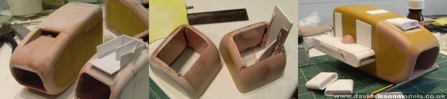
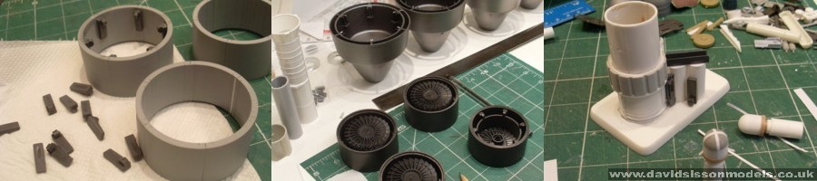
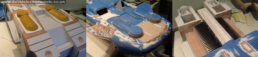
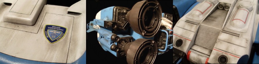
The engine units were full scratchbuilds starting with shapes formed in MDF, plastic, and filler. The original plan was to use these but I decided to cast the shape in fibreglass instead. These shapes were revised many times before I was happy with them. I kept placing the units in position and adjusting the various spacings and dimensions to get them to match up to the hull - certainly the upper engine changed a fair bit during this process - and I think I was slightly confused by my reference photos showing the two studio models, which appear to have differences in these areas.
When I was finally happy the front inlet areas were sawn off and the recesses drilled out and formed using car filler.

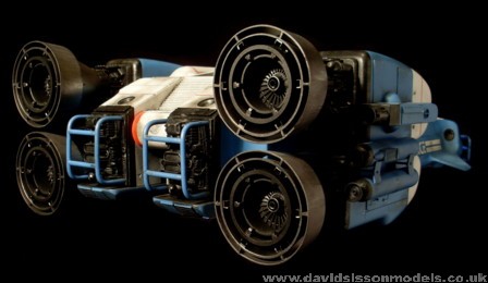
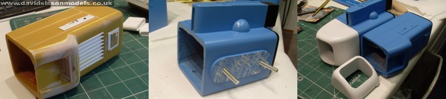
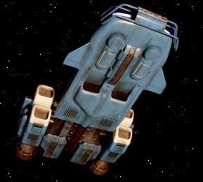
The engine units on the two big studio models did vary slightly so I just picked the details that I preferred, with most of it done in plasticard with a few modified model kit parts. There are a number of what appears to be kit parts on the engines, but I failed to identify any of them and had to resort to 
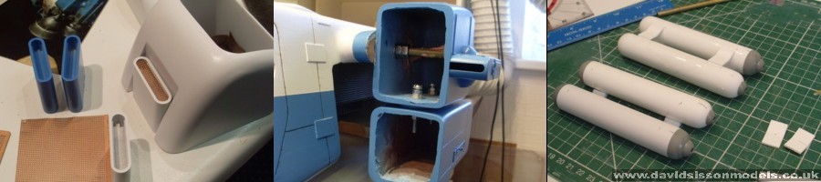
scratchbuilding copies. The twin missiles on the sides were large plastic knitting needles with some plasticard wrapped around them to bring them up to the correct diameter, with the ends being formed from domes taken out of the Revill Gemini kit. Other similar domes were cut down to make both the front nose and rear thrusters. The small intakes were formed in plastic sheeting with the curved edges made by splitting a section of plastic tube down the centre, and then the grill was cut from a fine metal mesh.
To hold the engines in position they were internally bolted to threaded metal rods, which were fed right through the model's hull. The two units also had steel bolts holding them together, with further bolts sticking out of the lower engines as mounting points for the rear bells.

The engine bells gave me a bit of a headache due to there size. I began by making the shape of a bell and managed to almost get the shape straight away by gluing together some plastic bells that I had in stock. The exact shape was achieved as usual with the application of car filler and plenty of sanding.
I then heat-formed/vac-formed numerous sheets of plasticard around this former to try and get some decent perfect pulls. Unfortunately all the ones I made had flaws due to the nature of the process, which stretch's the plastic. If you don't do everything perfectly you usually get a result where parts of the finished item are thicker than the rest, and some areas can be wafer thin.
As the engine bells needed to be reasonably strong I decided to glue two mouldings together, one inside the other, to beef up the weakened plastic. As part of this process I also created another shorter moulding of just the end section, which blanked off the bell and made it more ridged. When I glued all these into one-piece I could rotate the various mouldings to match the thick area of one to the thin area of another, thus creating an even thickness all round - and especially on the rim where it would visibly show up.
After final sanding I decided that the finished bells were still a bit weak in some areas so I poured a small amount of epoxy resin in the top end and let it seep down inside the rim, filling up any internal spaces and creating a solid but still light-weight structure.
I also thought that I would have to vac-form the wider baffle ring that encircles each bell, but noticed that they were straight and didn't actually have a curve to match the bells. So I made them by simply wrapping two layers of plasticard around a former.
The internal details of the bells used sections of EMA plastic tube, and a lot of EMA Structural System Components for detail, and to hold all the various tube sections in place. The centre of the bells were blank on the original models with just light bulbs to create the engine glow. I needed something far more interesting for my display model so ended up using the engine rotors from Airfix 1/24th scale Harrier kits. (They have sat in my spares box for years waiting to be used on a project!)
One unexpected problem was simply setting the four bells correctly, getting them to appear straight from all angles, all flat facing at the rear, and still with the same small gap between each pair - it took bl***y hours to do!

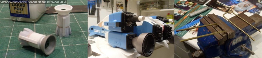
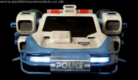
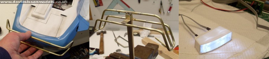
The bull bars were the next problem. They are 1/8th thick on the small 1/2-scale studio model so I assumed that they would be 1/4 inch on this size, but instead they are smaller at 3/16ths. Apparently they are also made from plastic tube, with a metal rod down the centre to allow them to be bent to shape, but that did make them easy to damage.
I decided to go for an all-metal build using brass rod. I started by bending two lengths into a U-shape, added the side angle, then joined them together using two short lengths of Brass tube sleeving, which allowed me to then adjust the width with ease - the tube would be hidden when I attached the bargeboard. The centre pipe was now made in the same fashion, and soldered into place with cross bracing and the support mounting to create a strong unit.
I was thinking of doing the rear units in plastic but, for durability, I decided to build them in brass also. These rear bars protect some complex detailing which luckily I didn't have to make, because many years ago I did some repair work on the Space Precinct Suburb model, noticed the same castings were on the bottom of it so made a quick mould off one!

I have started adding lights to some of my models and the Police Cruiser was calling out for them to be used, especially for the rotating beacons. On the studio models a motor rotated reflector cups around two bulbs, but as I didn't want a motor or the noise that might go with it I bought two sets of flashing LEDs off ebay. These sets are very useful as they have a controller allowing me to set the flash sequence and the speed, or have some of the lights permanently on. This combination would give me the beacons, headlights, and a flashing navigation light on the roof and belly.
Each of my beacons consisted of four LEDs mounted in a circle, each one flashing on and off in a rotating sequence. The bulbs were set in tubes buried in the roof, with bits of roughly angled perspex glued at the ends to distribute the light with the help of some silver foil backing. To help break up the obvious four separately blinking lights a fifth LED was set in the middle of each beacon that flashed in a different sequence. The outer casings were made from perspex sheets with the curved edges cut from EMA acrylic half-round rod; the red adhesive film is lens repair tape from a motorcar accessory shop.

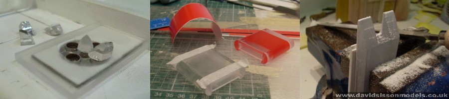
For a long while I intended to have the model sitting on its tricycle undercarriage, but I prefer the flying version which meant that I only had to build the footpads. The basic forms were created by gluing several layers of perspex together and then shaping them using a beltsander, with detail areas added using plasticard. Unfortunately I didn't have matching ridged plasticard (or whatever it was originally) for the tread pattern, so had to do it the hard way by gluing dozens of individually cut plastic strips into place.
The model had been painted during construction using automotive spray paints, Appliance White and Lada Adriatic Blue. Finally the side windows were added. I cut them from thin transparent plastic sheets, which were painted Black on the inner sides, and then inset into the hull. The windows on the original models had almost a matt finish, because they were dulled down to kill of the reflections. However I decided to keep mine glossy so they look more like glass, although I have dirtied them up with weathering powders.


Weathering was done using mostly black power paint, sealed on using Letraset matt fixative spray.
The various coloured stripes are Trimline tapes, available from model shops.

The precinct logos are original unused studio prints supplied by model maker Chris Trice - who worked on the series and supplied some important information for this build - my thanks go to him.


Back to INDEX

Article and photographs copyright David Sisson 2014